


BEFORE YOU BEGIN
First thing to do is to check whether your controller is setup for the PWM signal. Make sure GRBL 1.1 is flashed to your controller.
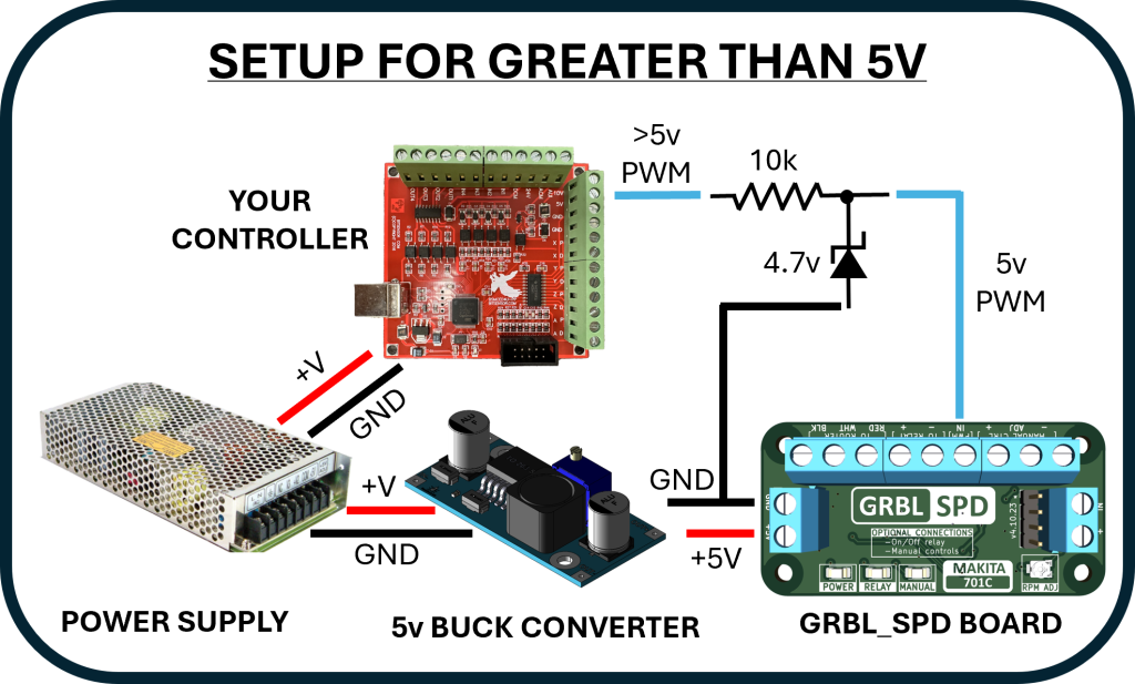
- If it is then with your machine turned on and using your favorite sender software, measure the voltage on the PWM (Arduino pin 11) while you adjust the RPM in the software. It should read voltages between 0v and 5v and change up and down with the software. If it does than you’re good to go.
- If it doesn’t than you will need to re-flash your controller. There are many resources on how to do this on the web.
FLASHING GRBL:
- Make note of all your machine settings on your controller.
- Download GRBL 1.1 latest version.
- Uncomment enable variable spindle in config.h.
- Flash to your controller.
- If machine settings are gone enter them from notes.
Now that you’re ready to install, here is what you need other than what is provided.
- Wire long enough to run from the GRBL_SPD to the router (5 wires) and from the GRBL_SPD to the optional manual controls (5 wires). In the range of 22 gauge as all these connections are low voltage and low current. Shielded cables are recommended to protection from interference.
- Standoffs or other method to mount GRBL_SPD inside control case. Old computer motherboard standoffs, PCB adhesive standoffs (Amazon) or however you see fit.
- Soldering iron or connectors to make the connections inside the router and to the optional switch with potentiometer.
- Electrical tape or heat shrink.
- Small zip ties if necessary to keep things tidy.
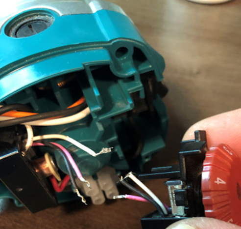
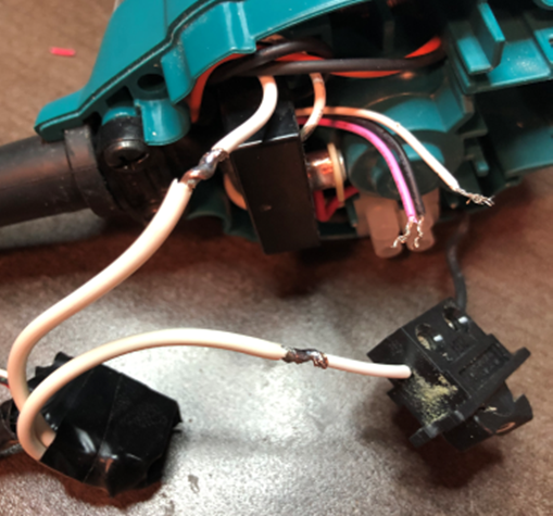
THE ROUTER:
Start by removing the router and remove the four screws holding the cap. Once open, run the wiring through the cover before making any connections. Now locate the red/white/black wires from the speed dial. Cut these wires and remove the Makita dial making sure there is enough wire left to make the connections. Connect the Makita red/white/black to GRBL_SPD red/white/black (refer to connection diagram). Locate the white wire from the Makita switch. Cut the white wire leaving enough length to make connections to both ends. Connect high voltage wires from relay to both ends of the cut white wire (refer to connection diagram). Connect low voltage wires to remaining connections on the relay(refer to connection diagram). The relay can be placed in the cavity on the opposite side of the main power connector or where the speed dial used to be. Screw the top of the router back on making sure not to pinch any wires and mount router back onto CNC.


OPTIONAL MANUAL CONTROL:
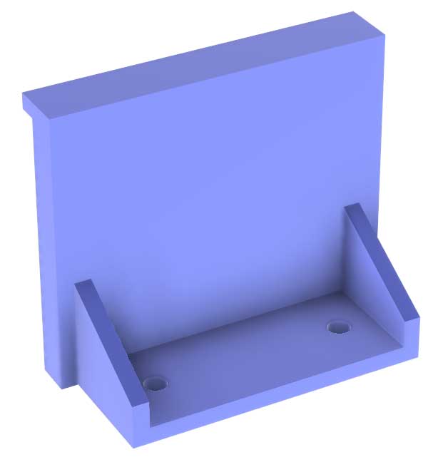
If you have downloaded and printed the stl file provided here then start by running the wires through the printed hole at the back. If your wires are going to go downward from the enclosure then start by connecting the wiring to the potentiometer (refer to connection diagram). Mount the potentiometer and the switch into the 3D printed enclosure. Connect the remaining two wires to the switch. This enclosure is made to snap onto the Millright Mega V leg. If not using this enclosure then do as you need and make the same connections as per your mount.


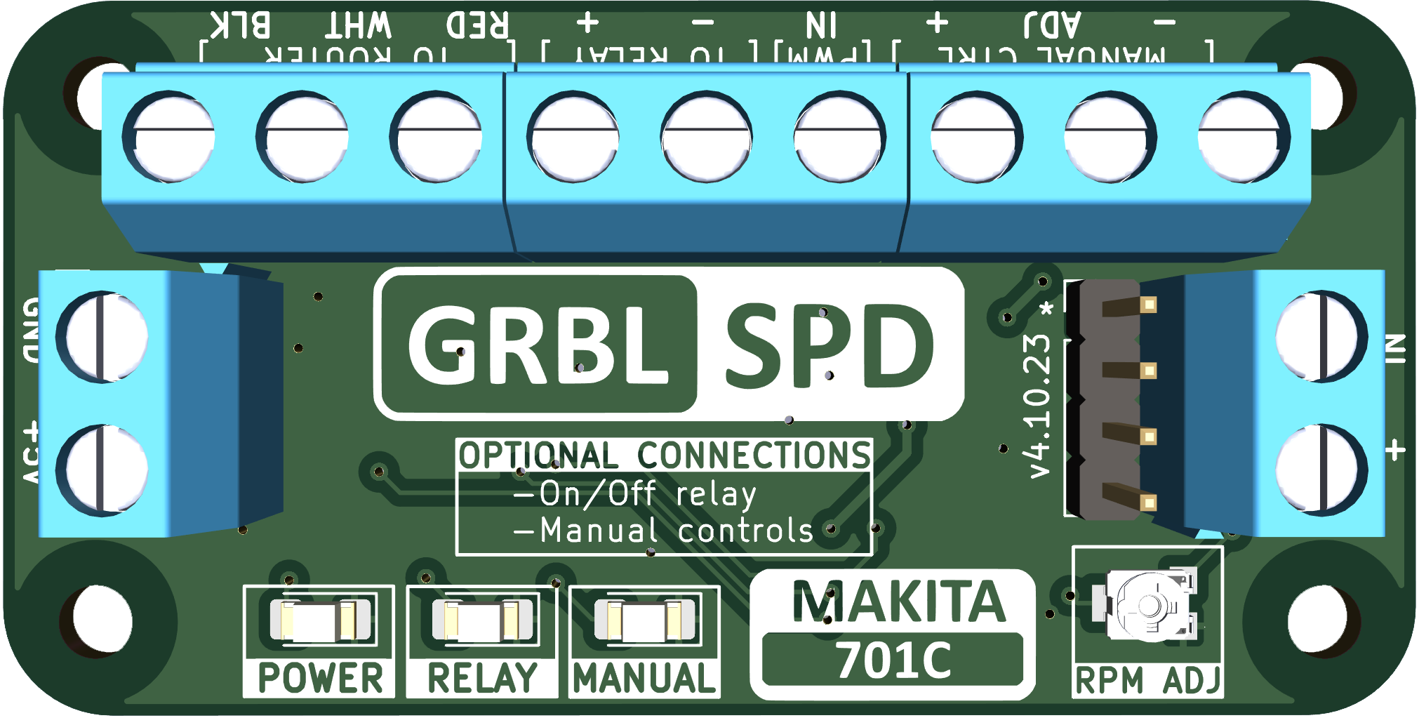
GRBL_SPD CONNECTIONS:
Run the wire from the router to the control box through the drag chains if equipped. Run the wires from the manual controls if installed. Make the router and manual control connections to the GRBL_SPD board (refer to connection diagram). Connect the PWM wire to the GRBL controller. Connect the 5v power and ground to the GRBL controller. Take a moment to check all connections.
CHECKS:
- Turn on you CNC with the computer connected and the sender software running. Check that the POWER ON led is on.
- Turn the manual control switch on if you have it. The spindle should be running at what the dial is indicating. Check that the RELAY ON led and the MANUAL ON led are on. Turn the knob from left (10000 rpm) to right (30000 rpm). If the RPM is reacting opposite to the dial then the potentiometer wires have been connected incorrectly. Reverse the (+) and (-) wires at the GRBL_SPD board.
- In your sender software be sure to set $30 to 30000 and $31 to 10000. Also make sure if there is a configuration section in the software, be sure to check that the min and max rpm are set the same. You may need to restart the software after changes are made.
- With manual turned off, start the spindle with the software. Adjust to different RPM to ensure it’s functioning. If it’s not then check your connections and/or ensure that the variable spindle option is enabled in GRBL with a voltmeter.
- If all is well and you have the manual controls, turn the spindle on with the software set at 15000 rpm. Set the manual dial to 30000 rpm and turn on the switch. Rpm should not have changed. Slowly turn the dial down towards 15000 rpm and when it is close, the manual control will take over. If the switch is turned off it will revert back to the software setting. If you’re in the middle of a path, leave the switch on until complete.
- Test your M3, M5, S##### commands.
Now you can set your speeds for each bit in your cad software of choice and your router will automatically be set to your required speed. When your path is finished the router will turn off when complete.
NOTES:
- The GRBL_SPD board you receive has been tested and calibrated with a Makita 701C router. There could be slight differences in routers but the variance in RPM shouldn’t be too drastic. If you have a handheld tachometer then you can test and adjust the RPM with the trimmer resister if necessary. In your sender software of choice turn on the router and set it for 10000 rpm. Take a reading with the tachometer and adjust the trimmer until it’s as close to 10000 as possible.
That’s it, congratulations you’re done!
Any questions drop me an email at jon@jsharrison.ca or my facebook link on this site.
