
WHAT DOES IT DO?
Changes from V3:
- 20 Mhz processor
- Improved RPM accuracy
- Improved smoothing for ON/OFF/RPM changes
- Auto off when using manual override
- Has same footprint and connections as previous model
Now available on Tindie! and Ebay!
Through software this project allows for the control of a Makita 701C router by a GRBL controller. The GRBL_SPD uses power connections and the PWM output from an Ardiuno controller (5v, ground and 0~5v). This gives your software the ability to control the router’s RPM(10000 to 30000) and on/off states. Now it’s easy to set your bit RPM in your Vectric tool database and automatically set the router to the RPM in the gcode file. Some people have had issues with the speed dial on the router moving while working. I’ve not yet had this happen but the potential problem is eliminated. You’re now able to control the router through your software of choice, your gcode file or by sending the M and S commands. If you are one who trusts your machine by walking away while in progress, the router will automatically stop at the end of the process.
The GRBL_SPD is an analog integration to the router so there will be a deviation in RPM in the range of a +/- 100 rpm and up to +/- 250 in the 25000 rpm range . On the board is a trimmer to help adjust for this by fine tuning at 10000 rpm. Optional terminals are provided to add a potentiometer and switch to have manual controls. This is handy for experimenting with the RPM for a new CNC bit or if you want to have manual control at the front of the CNC instead of reaching for the router. Also, if you need to adjust the RPM on the fly, you can either use the override of your software or by turning on the manual switch. The potentiometer will override the software control. To prevent a large jump in RPM, when you manually override, the override will not kick in until the dial is within 2% of the auto spindle RPM setting.
Do to the many different CNC configurations available, you will need to provide your own wire at the length needed and mounts for the GRBL_SPD board. All can be found on Amazon, Mouser, Digi-Key, Newark and so on. Mounting holes for the board are m3 so you could use motherboard standoffs from an old motherboard or order adhesive mounts from your supplier of choice. Five wires are needed to go to the router and five to the manual controls. 22 gauge is sufficient. Best to use shielded wire to avoid interference and stranded wire for flexibility. Soldering the connections to the router and manual controls is best but connectors will do.
BASE KIT:
- GRBL_SPD circuit board
- 10A Relay for spindle power
OPTIONAL MANUAL CONTROL KIT:
- Potentiometer and knob to adjust speed
- Toggle switch to enable/disable manual control
- This has been made an option as many folks will already have these parts kicking around.
NOT PROVIDED:
- Wire from controller to GRBL_SPD.
- Wire from GRBL_SPD to spindle.
- Wire from GRBL_SPD to manual controls
- Standoffs/screws to mount GRBL_SPD circuit board
- Mount for manual controls.
Downloadable stl files are provided on the instructions page to 3D print a manual control panel. The MegaV file snaps onto the leg of the Millright Mega V CNC. The other uses screws to mount.
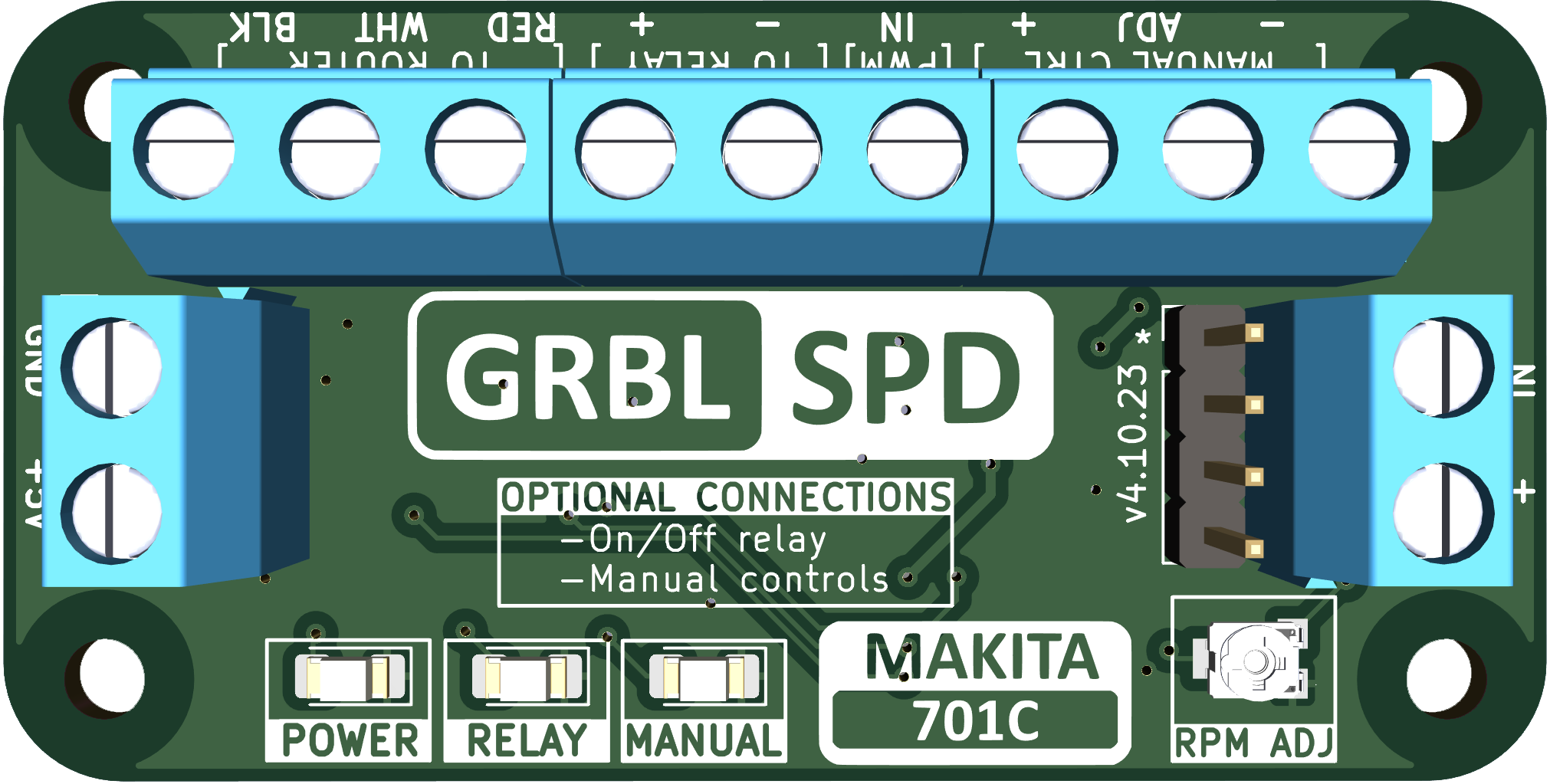
GRBL_SPD
GRBL_SPD V4
RUNNING GRBL_SPD in the MAKITA 240v 700C
Below are a couple of videos from Derek in Australia installing the GRBL_SPD in the 240v Makita 700c. Thanks Derek!